An oscilloscope is a device that captures a live signal from a test circuit and displays it on a screen. The signals are plotted on a graph to show how they change with time. The vertical (Y) axis represents the voltage measurement, and the horizontal (X) axis represents time.
Apart from capturing the signals, the digital oscilloscopes offer 2 other functions. It automatically measures various signals such as peak-to-peak voltage, frequency, duty cycle, and rise time. For signals that encode information, it decodes the information ad displays it on the screen.
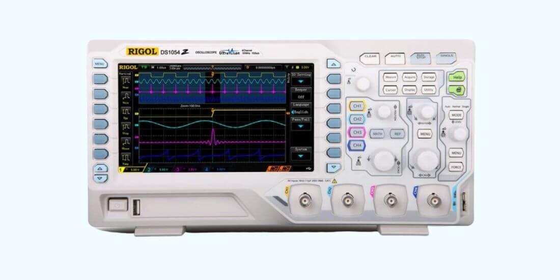
Let’s look at some of the essential oscilloscope functions. These functions will help use the device to tackle specific measurements easily. It consists of three main functions, i.e., horizontal, vertical, and trigger.
Horizontal Functions
- 10 x magnifying glasses: the function helps you zoom in directly into an area without changing time and other settings. It magnifies the image in a horizontal direction without affecting the voltage level.
- X position control: it controls the horizontal position of the electron beam without changing the time
- XY switch: it changes the coordinate system from the voltage-time to XY. It displays the voltage on channel one along the X-axis, while the voltage on channel two is shown on the Y-axis.
- Horizontal scaling control: it adjusts the electron beam’s deflection speed about time in ms per unit.
- Variable: the variable-length settings allow you to fine-tune the electron beam step by step on your respective set of horizontal scaling units.
- GND: it is the earth connection of the housing
- Switches between Chop mode and Alt mode: you can use this switch to toggle between Chop and Alt mode. The first and second channel’s signal is alternately displayed for each horizontal channel of the electron beam in chop mode. On the other hand, Alt mode displays the first and second channel’s images simultaneously.
Vertical Functions:
- Position: the knob helps in adjusting the electron beam position to align with a coordinate system.
- INV: the switch reverses the current channel by inverting the signal input’s polarity. When the voltage’s negative value is displayed, the electron beam image is ahead.
- Vertical scaling controls: also known as Volts/ Div control, is a slider used for vertical scaling. It determines the height of the electron beam in small graduation steps.
- Variable: you can fine-tune the electron beam steps by step on your respective vertical scaling unit. It also measures ripple voltage with this device.
- AD/DC switch: the switch shows how the measurement signal is coupled. AC alternates voltage while DC components are filtered out.
- GND switch: the switch removes electron traces from the display.
- Channel-1 Input: it allows you to connect the cables of the respective channel.
Trigger Functions:
- AC: the AC switch suppresses the AC voltages components selectively. It doesn’t jounce when signals with a lower cut-off frequency than expected.
- HF: this High-Frequency mode suppresses interference signals such as low-frequency signals.
- DC: it corresponds to the DC voltage; all signals from 0 HZ lead to triggering.
Display Functions
- Power On/Off: the on/off switch turns on and off the device when not in use. It has a small neon tube on the analog model and LED in a digital oscilloscope, which lights up when the light is on.
- Trace rotation: it ensures fine-tuning of the horizontal track with the raster lines.
- Intensity: the rotary control brightens and dims the electron beam on the screen.
- Focus: you can adjust the electron beam sharpness.
- Calibration Point: the calibrator connector is used to obtain a uniform square wave signal with a stable voltage and frequency.
Oscilloscope Math Functions
Math functions play a critical role in creating custom parameters with arithmetic relationships. It enables you to divide, multiply, add and subtract or rescale parameters. You can use this function to invert waveforms by multiplying voltage and current to find power or integrate a waveform to find energy and Joules.
Amazingly, you can combine parameters to calculate other parameters that basic oscilloscopes cant handle, including the crest factor of a wave or measuring the FM signal modulation index. You can ski use Processing Web Editor if you want to handle more complex custom math functions.
For instance, waveform analysis can be a complex task if you need to link together with math functions, and parameter math. The editor helps in giving a graphic construction and model like math and processing chains.
You can cascade functions with the help of this WebEdit or contain things like Matlab scripts. The preview function allows you to add a window that displays the output of any operation. You can see if what you are putting together is giving you what you expected.
The device can convert a time-domain waveform to the frequency domain, making it a useful tool for users. Fast Fourier Transforms (FFT) offers a standard math operation on the oscilloscope. To enhance its capability, you can use Spectrum Analysis software to simplify the FFT process. It provides an interface that is familiar to every user.
The install process of an FFT is simple and straightforward. Here are the steps
- Select the center frequency, resolution bandwidth, and span, and the software will set the proper sampling rate and time domain.
- An automatic peak-detect function shows all frequency peaks and displays them on the screen while creating an interactive table of the peaks.
- The FFT as a spectrogram shows how the spectra change over time.
Oscilloscope Calculations
AC Amplitude
If you calculate alternating current (AC) amplitude, start by plugging the AC signal into one of the probes before optimizing the signal. You will measure the signal’s amplitude by counting the number of vertical divisions between the signal’s highest and lowest points. You need to multiply the number of vertical divisions by your volts setting to get the amplitude in volts.
AC Frequency
For measuring alternating current frequency, you should plug the AC signals into one of the probes and optimize the signal. Count the number of horizontal divisions from high point to the next of your oscillating signal. Now, multiply horizontal divisions by the time to find the period.
DC Signal Voltage
For DC (Direct Current), turn on the oscilloscope without connecting the input probe. The Dc signal will be flat on your display. Place the device line over the zero volt level with the vertical position setting. Plug the DC signal path into one of the inputs. After plugging in the signal, you will realize the line moves on the vertical axis. Count the vertical divisions that your line shifts and multiply with the number of vertical divisions by the volts to find the DC signal voltage.
Types of Oscilloscopes
There are 2 types of oscilloscopes, i.e., analog and digital. An analog oscilloscope uses continuous variable voltage and an electron beam to display the input voltage to the display directly. It also has lower bandwidth and fewer features compared to digital.
- Digital oscilloscopes use input signals with an analog to digital convertor, and the reading is displayed. This category is further divided into:
- Digital sampling oscilloscopes: it is used for analyzing high-frequency signals up to 5o GHz.
- Digital storage oscilloscope (DSO); is equipped with memory to store waveforms and display them after some time.
- Digital Phosphor oscilloscopes: it uses a parallel processing architecture to allow it to capture and display signals.
Uses of Oscilloscopes
Firstly, an oscilloscope is used to display changes in the electrical signal over time. It ensures that voltage and time are graphed against the scale. The waveform is analyzed for multiple parameters, including rising time, time interval, amplitude, and distortion.
An analog oscilloscope, since the calculations need manual measuring of the waveform and calibrated scales displayed on the screen. For accurate results, you need to adjust the oscilloscope to get a similar signal on display.
It allows capturing of a specific event, and the waveform is displayed for a relatively long time. It also displays events that are too fast.
Additionally, it can be used for the maintenance of laboratory equipment. It analyzes the automotive ignition system or displays the waveform of an electrocardiogram.
The oscilloscopes used in Cathode Ray Tube (CRT) are equipped with a thin display panel, fast analog to display converts, and digital signal processors to maintain the display of a single signal.
The tool can also be used for audio to troubleshoot and malfunction electronic equipment. It reveals that the circuit is oscillating. You can use the oscilloscope to trace the signals when connecting amplifiers, electronic oscillators, and electronic mixers.
You can also use the device to check the circuitry. Newly designed circuits tend to misbehave due to error voltage, electrical noise.
Lastly, most digital electronics operate using signals. The oscilloscope helps in capturing the electronic events that can cause ineffective operation.
Oscilloscope Terms
Bandwidth helps to determine how the oscilloscope measures a signal. Increase in signal frequency makes the device to accurately display the signal decrease.
Sample rate: refers to how frequently the device takes a snapshot of the signal. It is measured in a sample per second. The higher the sample rate, the more accurate waveform is displayed.
Waveform rate: it is how quickly an oscilloscope gets waveforms. It is specified as a waveform per second.
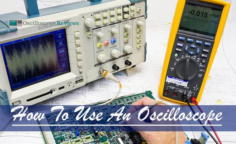
How to Use an Oscilloscope
Are you wondering how to use an oscilloscope? Here is how to do it:
Turn on the oscilloscope: Press Power or Line switch, and a flat line will display. Make sure you connect probes to the scope as well.
Connect to an Oscillating signal: Most oscilloscopes are equipped with a built-in frequency generator to emit a reliable set-frequency wave. If the device doesn’t have a waveform generator, you can upload the code to an Adriano to generate the signals.
Trigger: After connecting the signal via the probes, signals will display on the screen. You can move horizontal and vertical function switches to maneuver the waveform around the screen. It zooms in your waveform by rotating the knob clockwise, and if you rotate it anti-clockwise, it zooms out. You can rotate the trigger dial to see a trigger indicator rise up and down if the wave is not stable.
Start measuring: You can now start measuring with your oscilloscope.
Conclusion
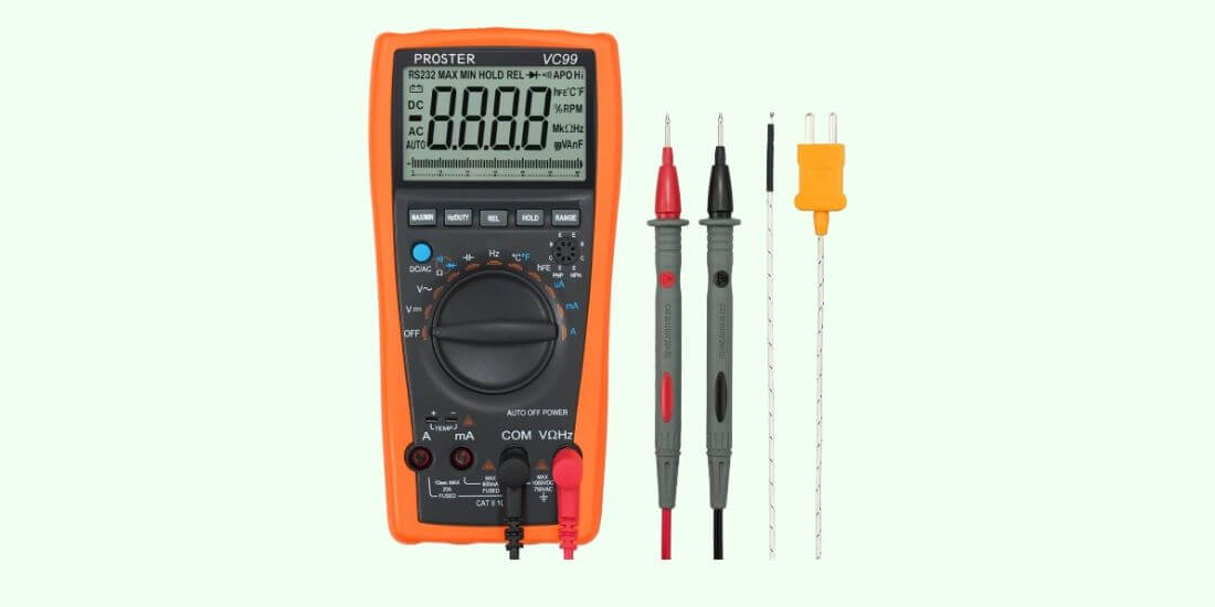
An oscilloscope is an essential device for any user, either beginner or experienced. If you are looking for something that can provide more information than a multimeter for troubleshooting your circuit, an oscilloscope is necessary. This article has covered functions, uses, different types of oscilloscopes, and how to operate them. I hope this information will help you to understand the oscilloscopes.
-
An oscilloscope is a powerful diagnosis and measuring tool for electric circuits. The advantage that…
-
Oscilloscopes are machines that measure and show voltage signals over a period of time. They…
-
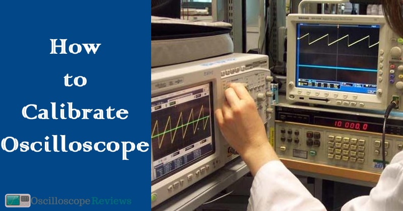
Oscilloscopes are a must-have for any electronics workbench. But how do you calibrate an oscilloscope?…
-
It is almost certain that you have drawn charts in your life or seen them…
-
Oscilloscopes are instruments used in the laboratory which is used to analyze waves of electronic…
-
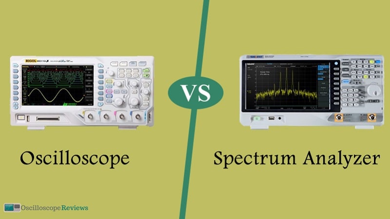
The primary difference between these two instruments is that with an oscilloscope, you can see…
-
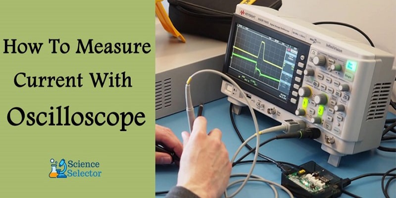
Although oscilloscopes are devices typically used for voltage measurements, not many people know that you…
-
Oscilloscopes are nifty gadgets that every person in the electrical field should have. They are…