
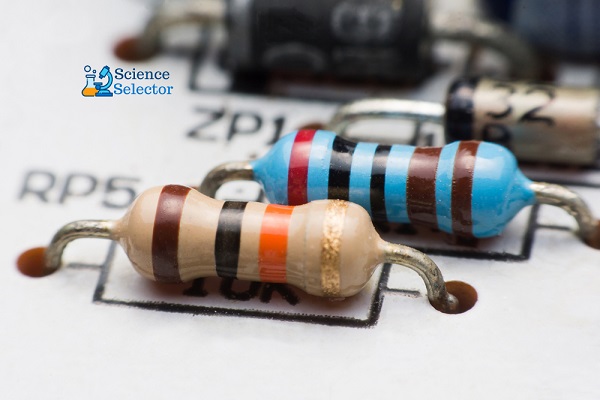
Tracks and pads on modern boards are getting smaller, and the boards themselves are often multi-layered.
All this significantly complicates the process of detaching an element to control its performance.
Therefore, the question becomes relevant: how to check a capacitor with a multimeter without desoldering it? Let’s try to find a solution.
How to Test Capacitor Without Desoldering
Difficulties of Verification
The process of determining the capacitance of a capacitor directly on the board is complicated by the presence of other circuit components – they distort the device’s readings.
First of all, this applies to elements with low DC resistance: fuses, inductors, transformer windings.
Determination of the capacitance of a capacitor without desoldering is possible only in the absence of the mentioned components.
Semiconductor devices – diodes and transistors – also have an effect.
Checking With a Multimeter
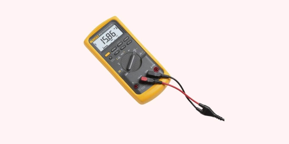
Using a multimeter, two parameters of the capacitor are checked: internal resistance and capacitance.
1. Internal resistance (Checks for Breakdown and Open Circuit)
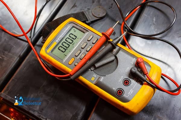
The multimeter is switched to the resistance measurement mode by setting the switch in the “Ω” sector to the upper position – for different models; it is 2 or 20 megohms.
Next, they touch the probes of the capacitor leads. If it works, the following happens:
- At first, the multimeter shows a low resistance – the capacitor is charged with the voltage supplied to the probes;
- As the charge in the capacitor increases, the resistance gradually increases and eventually reaches a very high value: on display – a value over 2 MΩ or “1” (infinity symbols).
Different behavior of the device indicates a malfunction of the element when the resistance:
- It turned out to be below 2 MΩ: the capacitor is broken (conductivity appeared in the dielectric between the plates);
- Immediately became infinitely large: output breakage.
Capacitors are divided into two types: polarized and non-polarized. The first ones are sensitive to the polarity of measurements. If it is confusing, they fail by applying a positive potential to the “minus” terminal and a negative potential to the “plus” one. The “minus” terminal is recognized bу the “bird” mark on the capacitor body.
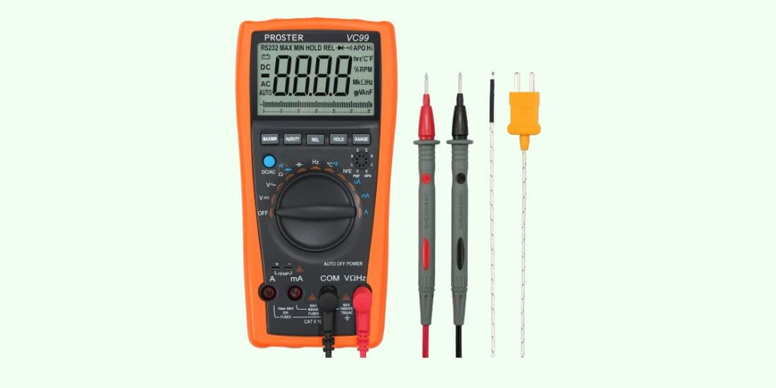
In a multimeter, the potentials are distributed as follows:
- Port “COM” – negative: according to an unspoken rule, a black probe is included here;
- Port “V / Ω” – positive: it is customary to turn on the red probe.
In the presence of a knowingly serviceable capacitor of the same brand, the state of the investigated person is checked by the comparison method:
- Measure the resistance of a working capacitor;
- The same is done for the investigated element;
- Compare the rate of change of readings on a multimeter.
An analog (pointer) tester is more suitable for this method: a smoothly deflecting arrow reflects the change in resistance in real-time.
The capacitor is checked in a discharged state; otherwise, electric shock or damage to the multimeter is possible.
The discharge method depends on the capacity:
- Small (low voltage): short-circuit the terminals with a screwdriver; l
- Argue (high voltage): short-circuit the terminals with a 10 kΩ resistor.
The resistor is held with a tool with insulated handles.
2. Capacity

Capacitance measurement is possible if there is a special function in the multimeter. Such devices have a “CX” sector on the front panel.
The capacitor is connected in two ways:
- Some models have probe connectors marked “CX”;
- Others have two pads marked “+” and “-” in the “CX” sector.
When the probes or pads contact the capacitor leads, the capacitance value is shown on display. The data obtained is compared with the numerical indicator indicated on the capacitor case, after which a conclusion is made about its suitability.
The switch should be installed in the “CX” sector at the position with the nearest higher value in relation to the expected capacity. There are 5 positions in an industry with data from 20 nF to 200 μF.
This test method is not suitable for capacitors with a capacitу of less than 0.25 μF. They are checked with a special device – an LC meter.
In the absence of a function for determining capacitance, the capacitor is checked as follows:
- Charge it from a DC source. The source voltage is about half that of the capacitor. For a 25 V cell, a 9 – 12 V source is sufficient.
- After waiting a few seconds, which is usually enough for a full charge, the radio component disconnects from the power supply. The voltage at its terminals is measured with a multimeter.
The meter is configured as follows:
- A black probe is plugged into the “COM” port;
- Red – to the “V / Ω” port;
- Switch: to the DC voltage measurement sector (“DCV” or “V-“) to the position with the nearest higher value relative to the expected capacitor voltage.
How to Check Without Desoldering
It is very problematic to check the capacitor directly on the PCB. First, the faulty electrical device must be completely de-energized. It is also necessary to achieve the discharge of all capacitive elements in the circuit. A no-solder test can show the resistance values of elements soldered side by side. But the check can still be carried out using the tweezers indicator.
The First Way
The first way is the easiest. The subject is checked by a tester and called with a multimeter. The device is put into resistance test mode. It is also worth considering the polarity. The multimeter probes are connected to the terminals of the capacitor, and the resistance is measured. It should be borne in mind that the value obtained has no practical use since it may indicate another element. In this way, you can check the capacitive part for a short circuit. If the displayed values begin to rise gradually, then the printed part is charged from the tester and is in good working order.
Second Way
The second method requires soldering a capacitor with the same values into the circuit next to the item under test. Soldering must be carried out in parallel. Both elements are measured on a de-energized board.
Third Way
A situation often arises when several capacitors are on the board, and it is tough to determine which one is faulty. Soldering each is quite laborious; they often fail when heated. To check without unsoldering, it is necessary to measure the output voltage. It must be the same as indicated on the element body. If there is no voltage, then the part is broken or shorted. If the voltage is less than the optimal value, the cell has lost some of its capacity.
Without desoldering, you can visually identify the faulty element. The condenser may burst, be damaged on the case, carbon deposits, or swelling.
Spark Test
In the absence of a measuring device at hand or in the case of a large capacitor capacity, it can be checked “bу eуe.”
The cell is charged, and then its terminals are closed with a metal tool with insulated handles. Wear rubber gloves on your hands.
A bright spark accompanied by a characteristic sound indicates that the capacitor is working properly. If the discharge turns out to be sluggish, it is time to dispose of the radio component.
To obtain comprehensive information about the state of the capacitor, a multimeter with a capacitance measurement function is required (there is a “CX” sector on the control panel).
But even a tester that is not equipped with such an option will tell a lot about this element. Removing the capacitor from the board is not always required, but you should be prepared that when measuring on the board, the accuracy will be far from ideal.
-
Electricity is one of the fantastic inventions made over the past few centuries and has…
-
How do you feel when you wake up earlier in the morning and realize that…
-

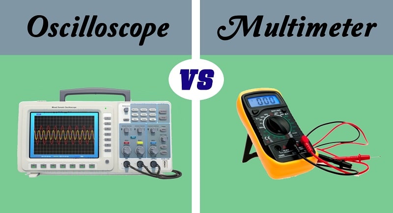
An oscilloscope is a device that captures a live signal from a test circuit and…
-
On devices, the current strength that they can withstand is rarely indicated. The main ones…
-

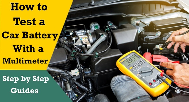
Your car running out of electricity can throw a spanner in your works for the…
-
Oscilloscopes are machines that measure and show voltage signals over a period of time. They…
-
Although oscilloscopes are devices typically used for voltage measurements, not many people know that you…
-
Unless you are a technician who needs to alternate between True RMS and automotive meters,…