Life is full of choices. Some are simple, like choosing between butter and ghee, whereas the confusing end is the analog Vs. digital oscilloscope. This article aims at teaching you all the differences between the two devices; their designs, scope of functions, and limitations.
In case you are in the circuitry industry, not once will you need to test the strength of the voltages you work with. Oscilloscopes make this process a breeze by sampling electronic signals to create waveforms. Some oscilloscopes feature LCD screens that display electric signs in discrete, readable texts and numbers.
Some oscilloscopes are also capable of triggering electronic beams or current. They enable you to vary the signals to ascertain what works best for you and the project you are working on.
A Brief History of Analog Oscilloscopes
As their names go, analog oscilloscopes refer to mechanical signal strength test machines as was invented in 1893 by French physicists Andrew Brondel. They were applicable until the early 2000s, when digital oscilloscopes took over the market.
The first analog oscilloscope was very simple in design, mainly built to register alternating current. This device used mechanical parts consisting of an ink pendulum that scribed information on a moving sheet. As a result, the bandwidth was small, between 10 to 20 kHz, making it not accurate.
In 1897, analog oscilloscopes’ scope took a turn for the better when Karl Ferdinand, a German Physicist, invented a cathode ray tube (CRT). This tube employed an electrostatic method to test for the strength of electronic beams. It also helped advance the frequency and the bandwidth of the analog oscilloscope. The devices could record and display signals in the Y and X-axis, forming waveforms.
The current analog oscilloscopes available in the market still use the cathode ray tube as their leading powerhouse. They have bandwidths of up to more than 20MHZ, making them ideal for a wide range of essential tasks. Even with that, there are advanced tasks that they cannot do, especially those that entail sampling unimaginably higher signal strengths.
A Brief History of the Digital Oscilloscope
As the scientists aimed at widening the analog oscilloscope bandwidth, they came up with the ADC (hybrid analog-to-digital converters). This advancement made it easy to sample and record accurate digital frequencies of even the lightest signal strength simultaneously. It led to the invention of the first digital oscilloscope in the early 1980s.
On the other hand, scientists in the digital screen display created compact display modules that quickly captured and displayed signals as they form. The combination of the ADC and the display module gave rise to three different types of digital oscilloscopes.
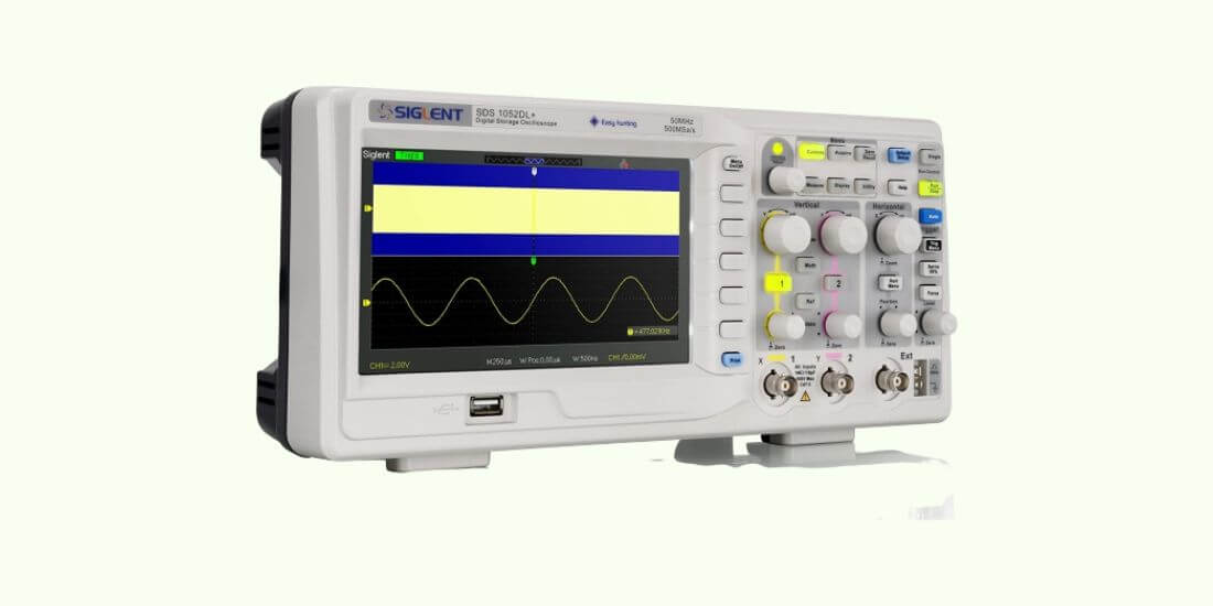
● Digital Storage Oscilloscopes (DSO)
Digital Storage Oscilloscopes are the most popular type in the market today. These devices analyze and store the input signals of electric current on a real-time basis. They can also trigger and display signs using either LED or LCD screens.
● Digital Stroboscopic Oscilloscopes (DsaO)
Digital stroboscopic oscilloscopes observe, measure, save, and process repeating current on an equivalent time scale basis. They also apply whenever you need to transfer the electric current to a secondary processor using a digital connection. Plus, some also install secondary devices for more advanced data exchange.
● Digital Phosphor Oscilloscopes (DPO)
DPOs work the same as the DSO—they record real-time frequencies of signals as they form. However, they integrate one more feature missing in the DPO to achieve a better representation of the signal. DPOs achieve the frequency-of-occurrence by tracing the intensity that a current display occurs.
Unlike DSOs, DPOs can trace multiple scope frequencies and present them better in a display. This function is even better in complex modulated analog signals that require robust analysis.
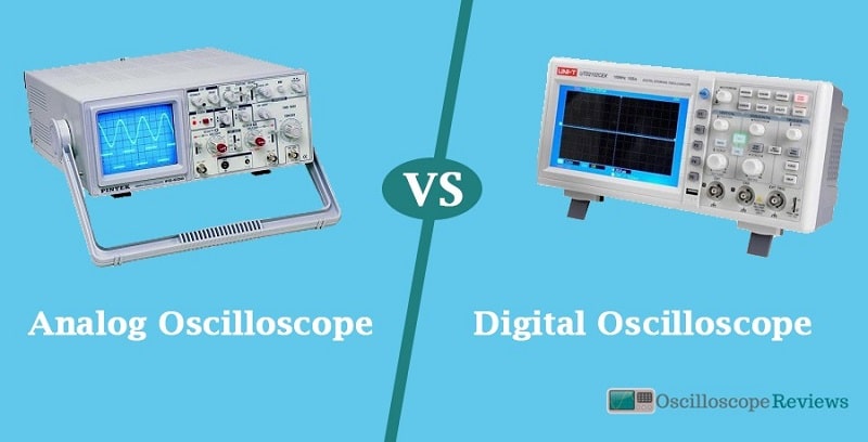
Analog Vs. Digital Oscilloscopes; the Differences
Analog and digital oscilloscopes differ in many ways; their invention years and period of general outlooks are just a start. In this guide, we condense the comparison to two main metrics—design and scope of function. In this section, you’ll better understand how each works and what they can do.
1. Design
Analog oscilloscope
Analog oscilloscope is designed with four main sections; display, trigger control, vertical control, and horizontal controls. At the center of all these is the CRT tube with controls that let users find, focus, and trigger the intensity.
The display section shows the wave formed during sampling. It enables you as a user to get timely results and also gauge the electronic currents for manipulation.
The vertical control applies whenever you want to control the amplitude of any displayed signal. It contains knobs used to vary the volts, a selector switch, and a vertical input instrument. Last in this section is the vertical beam position knob used to position the electronic beam at your preferred point of focus.
The Horizontal control section contains the knobs and switches you need to vary the base “sweep” of your waveforms. It comes with a selector switch that controls the second-per-divisions when sampling.
The last on the list is the trigger control section that contains all the instruments you need whenever you want to trigger signals. Just by a press of the button and a switch, you can set the trigger to go automatically after a certain period or after every sweep. It also has an EXIT selector for probing the triggers off. You can as well configure the signal to respond to either external or an internal event.
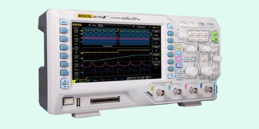
Digital Oscilloscopes
Initial digital oscilloscopes featured the same designs as their vintage counterparts, with the four parts mentioned above. The only distinctive feature that set them apart was the ADC and FPGA integration. Otherwise, they also used cathode ray tubes for sampling and displaying.
Modern digital oscilloscopes come with a small body and nano ADC. They also feature internally-integrated low noise drivers that keep them quiet. Lastly, some come with Quad storage that helps with maintaining samples for advanced processing and analysis.
2. Scopes of Functions
- Display
The Cathode Ray tube in the analog oscilloscope reads voltage and transfers the measurements to the display screen. Since the electrostatic deflection is fixed, the screen’s size is always 8 cm by 10 cm. You may not be able to find analog screens with larger screens than this. Also, the display resolution is a bit low. They are mainly used to test for voltages and temperatures.
Conversely, digital oscilloscopes come with different screen sizes, some as small as 4×2 cms. Also, the screen size differs from one digital oscilloscope to the other—for example, DSOs will have larger screens than the DsaO.
Digital oscilloscopes have an average of 8 bits screen resolution. Some can capture up to 0.4% distortion range in a signal when sampling. More advanced digital devices have up to 32 bits resolution. These oscilloscopes can test even noise and pressure vibration on different bases.
- Trigger
Both the digital and analog oscilloscopes can do post-trigger, pre-trigger, level-slope, and source triggers. But in case you are working on tasks that require advanced triggering, you may need to use the digital variants as they come with advanced for customized accurate triggers. Also, some digital devices are designed specifically for certain tasks, especially those that require specific formulation when triggering.
- Input Range
An analog oscilloscope’s input range is a vertical input amplifier that you can vary using the elements on the vertical control section. The first variants had a fixed input range.
Digital oscilloscopes, on the other hand, have input ranges from +/-50 millivolts to +/-50 Volts. The millivolts apply when sampling small signals, while the volts work best for more significant signals.
Also, the digital oscilloscopes come with probes for changing the input ranging. Some devices come with additional probes for zooming signals with lower input ranges. For example, smaller signals with less than 50 volts require higher resolution, so it’s best to use devices with 12+ bits and higher zoom capability.
- Memory depth
Analog devices do not have memory capability; they cannot store samples once testing is completed. Therefore, they do not have a memory rate.
Analog oscilloscopes have different memory depths from 1kb to hundreds of MBs, depending on the scopes. The size hardly affects memory depth in analog oscilloscopes.
- Sampling rate
Sampling rate refers to the speed at which an oscilloscope works measured by the number of samples it registers every second.
The sampling rate in an analog oscilloscope is fixed and determined by an oscillator that is clock-driven. Advanced analog models have rates of as high as 100 GS/s, while the least rate is 5GS/s.
The Digital oscilloscopes sample signals either mega samples per second (MG/S) or Giga samples per second (GS/s). The rate of sampling is variable, depending on the specs of your device. If you need repetitive sampling, the rate will be a bit higher to keep pace with the wave formation.
The Final Verdict
There is no one-fit-all oscilloscope that is better for all your functions. However, for more bandwidth, accuracy, and timeliness, digital oscilloscopes rule all the time. What’s more, they come with no-processors that cut on their size and weight, making them highly portable.
Analog oscilloscopes are also ideal for simple tasks. Their only downside is that they do not store data unless connected to a secondary storage device. This limitation makes them vulnerable to data loss.
-
Oscilloscopes are instruments used in the laboratory which is used to analyze waves of electronic…
-
Imagine a movie scene inside a hospital. What machinery do you see? Whatever you’re imagining,…
-
Electricity is one of the fantastic inventions made over the past few centuries and has…
-
In this digital era, electronic appliances are getting digitalized as well. So is the case…
-
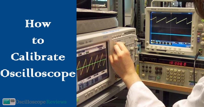
Oscilloscopes are a must-have for any electronics workbench. But how do you calibrate an oscilloscope?…
-
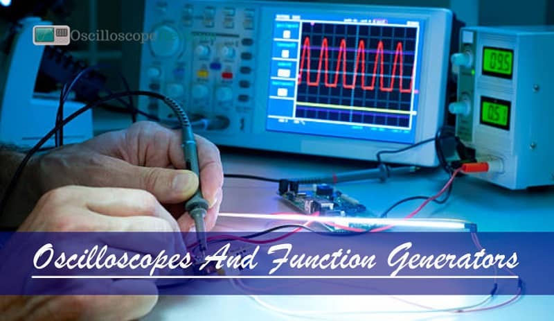
Some will argue that an oscilloscope and a function generator are the best instruments used…
-
It is almost certain that you have drawn charts in your life or seen them…
-
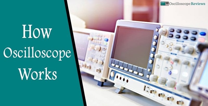
An oscilloscope or o-scope is a device that measures voltage. By using a probe it…