It is almost certain that you have drawn charts in your life or seen them in newspapers at one point or another. A significant number of these charts display the quantity of something. It could be the country’s exchange rate, the cost of corporation shares, or heart rate changes over a period.
On most occasions, the amount is plotted in the y axis (vertical direction) while the time is plotted in the x-axis (horizontal direction). Drawing and plotting such charts could take forever if you decide to do it manually. But, you do not have to feel overwhelmed and tired doing all this, yet an oscilloscope could easily do that for you.
Oscilloscopes make work easier by drawing and plotting charts. Below is more information about oscilloscopes, including their functions and how they work.
What is an Oscilloscope?
An oscilloscope is a handy tiny device that automatically uses signals to draw charts draws that you feed into it by hooking up to a piece of monitoring equipment, a piece of scientific equipment called an electronic circuit from probes.
It is also suitable to say an oscilloscope is a gadget that makes it easy for you to see how the voltage of other devices changeover a period by displaying a waveform of electronic signals. An oscilloscope will enable you to view voltages which are signals used to deliver information like an audio signal playing music on a loudspeaker.
An oscilloscope screen displays various things like the measured signal of voltage using a chart. The voltage is represented in both the x-axis (horizontal), which means time, and the y axis (vertical), representing the voltage.
How Do Oscilloscopes Work?
The traditional oscilloscope works in almost a similar way as the conventional television- using a cathode ray tube. Therefore, do not be perplexed when you hear some people referring to oscilloscopes as CROs or cathode ray tubes.
In traditional television, electron beams scan forth and back in a screen, which is most likely costed with phosphors-special chemicals- on its back. Every time screen is hit by the beam, the phosphors light up. The electrons then sweep across the entire screen and display the picture one sees in a concise period. They repeat this process repeatedly, so you end up seeing a moving image and not a still one.
In an oscilloscope, the electron beams work in an almost similar way, but they draw a graph instead of coming up with a picture. When you look at an oscilloscope and see a drawn line, you are practically looking at an electron beam wobbling upwards and downwards.
The electronic signals fed to the x and y connections become the x and y values on the screen chart. The traditional oscilloscope is a conventional device, and that’s why there is a one to one correspondence between these two things. If it sounds better, you can say the screen’s trace is an analogy of whatever you are measuring or studying.
How about the electronic oscilloscope? How does it work? Imagine if you were an oscilloscope, and you are holding a pencil at the zero point of a graph paper. Now imagine further that your hand is joined to two motors which are electric: The first one can move it in the horizontal direction (across the page from one side to another) and the other motor moving your hand by precise levels in a vertical direction (upwards and downwards). An electric circuit is then connected to the motors so that it can identify signals of different types.
Now, imagine if you connected a quartz clock, which is electronic, to the x circuit. Every time there is a ticking of the clock, a signal is sent to the motor making your hand move a bit to the right side. So, in a short while, your hand will move all of a sudden to the right side, and it draws a horizontal line as it progresses. How about if we connected the y side to an electronic device to detect the heartbeat of a person.
If the y and x circuits are connected simultaneously, your hand will have to move across the page, just like before. Still, it will also jump up vertically anytime your heart beats making a drawing of the heartbeat traces you see in dramas in TV hospitals.
If you use a TV screen and electron beam instead of a graph paper and pencil, you will exactly see how the oscilloscope draws its graphs. Every time a waveform passes through the y end, the electron beam will jump upwards. As this happens, a time signal makes the trace move from right to left in the x-axis (horizontal).
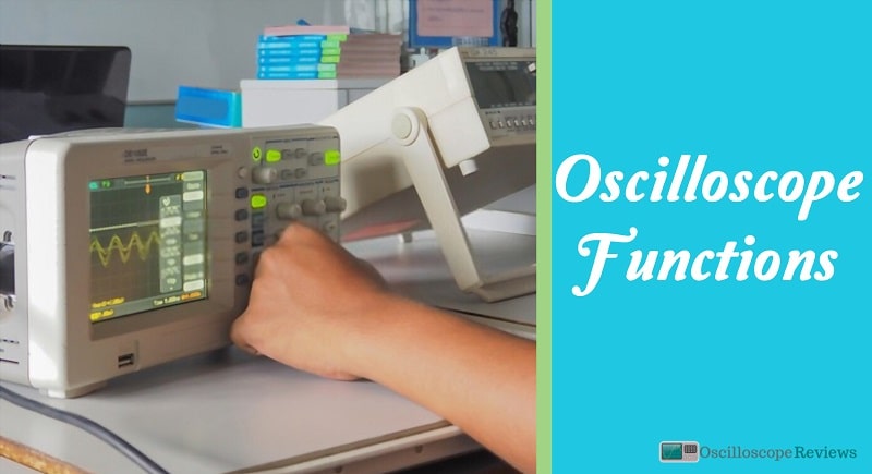
Functions of an Oscilloscope
Oscilloscopes display and test voltage signals in the form of visual representations and waveforms over time. The signs are plotted on a graph hence showing the signal changes. The y axis (vertical) represents the voltage measurement, while the x-axis (horizontal) represents time. Below are some of the functions of oscilloscopes.
Sampling
Sampling is when a portion of an input signal is converted to several discrete electrical values for display, ‘processing, and storage. The strength of each of the points sampled is equal to the amplitude of the input signal when the signal is sampled.
The input of the waveform looks like a series of dots as displayed by the oscilloscope. If the dots are difficult to interpret and are widely spaced as a waveform, they can be easily connected through interpolation- a process that connects dots with vectors or lines.
Plot waveform signal
Oscilloscopes are used to display live signals on its screen. A change in the movement leads to an update in the display by the oscilloscope. It will update its collection in real-time to reflect this change.
Decoding
This is a more advanced but common feature of modern digital oscilloscopes where they decode a signal that contains data. When two devices communicate, they use a specific protocol for data to travel between them e.g., in microcomputer and microcontroller applications, the main protocols used are CAN, I2C, UART, and SPI.
These protocols help describe how a value, like a character or a number, is encoded in a waveform in a particular shape. Such waveforms with the shape contain all the information. At the receiving end, a different device will translate the waveform to extract the data.
There are oscilloscopes with this decoding capability. They can eavesdrop on the communication between two devices and extract any information hidden in the waveform as it travels through the wire.
You can use an oscilloscope to decode communication between two devices and troubleshoot problems, confirming that your hardware is working the right way. However, even if oscilloscopes can decode signals, that is an additional feature. There are devices made specifically for that.
Triggering
Controls by the trigger allow you to display and stabilize a waveform repeating itself. The most common form of triggering is edge triggering. In this mode, the Slope controls and trigger levels provide the primary trigger point definition.
The Slope controls determine whether the trigger point is on the falling or the rising edge of a signal, and the level control determines the point where the trigger point will occur. When working with complex signals like various pulses, pulse-width triggering may be required.
With this, both the falling edge and the trigger level setting have to occur within a given period if these two conditions are met, the oscilloscope triggers.
Single-shot triggering is another technique where the oscilloscope displays a trace only if the input signal meets the trigger’s conditions; if the needs are met, the oscilloscope updates and acquires the display, after which it freezes the display to hold the trace.
Types of Oscilloscopes
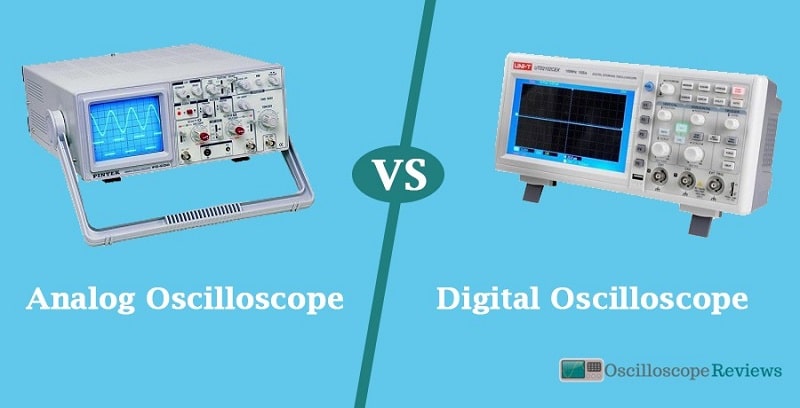
Analogue Oscilloscope
This was the first type of oscilloscope to become famous. This type used the cathode ray tube, and it was the main one used for testing for many years. Analog oscilloscopes were in use throughout.
The first analog oscilloscope was very large, and it contained very many thermionic valves and vacuum tubes. With the advancement of technology, people came up with new transistorized test instruments, much smaller and more efficient. However, they still needed to be deep enough to accommodate the cathode ray tube.
Indeed the analog oscilloscopes did not offer the same facilities as those provided by the modern oscilloscopes. Capabilities like the adjustable trigger, digital displays of the waveforms of voltage, accurate measurement of values, and markers were all absent in the analog oscilloscope.
The standards highly limited the previous test equipment there are today. However, the analog instruments still made it easy for electronic circuit design engineers to see the needed waveforms and were performing the basic functions as expected.
LCD And CRO
As earlier mentioned, oscilloscopes were previously based on cathode ray tubes which are relatively expensive, unreliable, heavy, power-hungry, and bulky. The more convenient LCD technology has been replaced, similar to CRT televisions, so man LCD screens have replaced the CRT oscilloscopes.
Rather than using mobbing electron beams to draw traces, LCD oscilloscopes use digital electronics to remove traces. They effectively mimic what was happening with the earlier technology. LCD oscilloscopes are very cheap and are compact- you can fit them in your pocket.
The traditional oscilloscopes used conventional technology, which displayed varying signals on the screen which correspond precisely to the calls you feed them with. On the other hand, LCD oscilloscopes are generally digital, and they make use of analog to digital converters to turn analog signals to numeric form and afterward plot the numbers on the screen.
Mixed Signal Oscilloscope
This type of oscilloscope effectively marries the functions of the logic analyzer and the am oscilloscope. It has various electronic circuit designs, which combine with digital circuitry and analog electronic circuit designs.
The analog oscilloscope input channels are present in this oscilloscope to look at the shape of waveforms and then look at the number of logic analysis channels for looking at different media’s digital state. Mixed-signal oscilloscopes were developed and introduced to meet this need.
This oscilloscope has two or more competent scope channels and several logic analysis channels, say eight or sixteen.
Plug-in Oscilloscopes
Since your smartphone, tablet, or computer already possesses an LCD or CRT display, you don’t have to buy an oscilloscope if you want to use one in your hobby. Some companies sell cheap plug-in oscilloscopes with USB connectors or similar leads for mobiles.
These connectors simulate the circuit in a traditional oscilloscope then display a trace on your mobile screen or PC. Doesn’t that sound convenient?
Final Thoughts
Technology is advancing with each passing day, and the vitality of oscilloscopes cannot be under looked. To understand how oscilloscopes work, you have to know more about how they display a signal. Analog oscilloscopes are way different from digital oscilloscopes in form, features, and function.
Digital oscilloscopes approach the problem differently and store offsets for the ranges without any input at the division until it is switched.
-
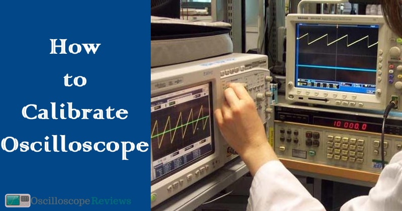
Oscilloscopes are a must-have for any electronics workbench. But how do you calibrate an oscilloscope?…
-
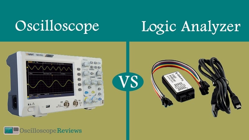
The oscilloscope and logic analyzers happen to be the most recognized types of test gadgets…
-
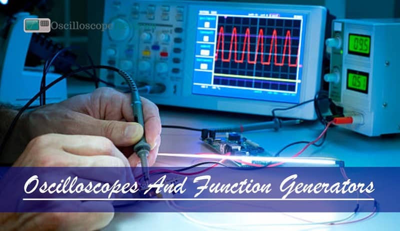
Some will argue that an oscilloscope and a function generator are the best instruments used…
-
The primary difference between these two instruments is that with an oscilloscope, you can see…
-
Life is full of choices. Some are simple, like choosing between butter and ghee, whereas…
-
An oscilloscope is a device that captures a live signal from a test circuit and…
-
Oscilloscopes are instruments used in the laboratory which is used to analyze waves of electronic…
-
Electricity is one of the fantastic inventions made over the past few centuries and has…